# BranchCAD user guide
> The complete user guide for BranchCAD, browser-based 2D CAD with real-time collaboration and Git-style version control. Edition 1.0, November 2026.
- Web version: https://branchcad.com/docs/user-guide
- PDF: https://branchcad.com/downloads/BranchCAD-User-Guide.pdf
- Command cheat sheet: https://branchcad.com/docs/cheat-sheet.md
- Open the app: https://app.branchcad.com/login
> **How to read this guide:** Commands are shown like `LINE`; their short aliases follow in brackets, e.g. `LINE` (`L`). Keys are shown as `Enter`. A step-by-step procedure is a numbered list. Every command is also listed on the separate **BranchCAD Command Cheat Sheet**.
## Contents
1. [Welcome to BranchCAD](#c1): What it is, who it is for, what you can do
2. [Getting started](#c2): Account, your models, opening the editor
3. [A tour of the workspace](#c3): Toolbars, panels, status bar, command line
4. [Commands & coordinates](#c4): The command line, aliases, typed points
5. [Navigating the drawing](#c5): Zoom, pan, overview, saved views
6. [Drawing objects](#c6): Lines, polylines, circles, arcs and more
7. [Drafting precision](#c7): Snaps, grid, ortho, polar, tracking
8. [Selecting & the Properties panel](#c8): Picking, windows, grips, quick select, groups
9. [Modifying geometry](#c9): Move, copy, offset, trim, fillet, array…
10. [Layers, linetypes & lineweights](#c10): Organising a drawing
11. [Text, tables & leaders](#c11): Annotation and text styles
12. [Dimensions](#c12): Seven dimension types and dimension styles
13. [Hatching & regions](#c13): Fills, patterns, boolean shapes
14. [Blocks, images & external references](#c14): Reusable symbols and underlays
15. [Measuring](#c15): Distance and area
16. [Layouts, sheets & plotting](#c16): Paper space, viewports, PDF output
17. [GIS & georeferencing](#c17): Real-world coordinates, maps, parcels
18. [Fence design](#c18): Fence runs, gates, elevations, materials
19. [Importing & exporting files](#c19): DXF, DWG, CSV, GeoJSON, images
20. [Sharing, collaboration & history](#c20): Links, live editing, comments, versions
21. [Settings & plans](#c21): Appearance, defaults, account, billing
22. [Keyboard shortcuts](#c22): Every key in one table
23. [Troubleshooting & FAQ](#c23): Common questions and fixes
---
## Chapter 1: Welcome to BranchCAD
*Introduction*
BranchCAD is a professional 2D CAD application that runs entirely in your web browser. There is nothing to install: sign in, open a model and start drawing — with the AutoCAD-style commands you already know.
**Built for real work on real sites.** Draw site plans, buildings and details to exact dimensions; place the drawing on its true map location; fetch parcels and building outlines; design fences with posts, rails, gates and a bill of materials; and plot finished sheets to PDF. Your work is saved automatically and can be shared, edited together in real time and versioned like code.
- **Precise drafting:** Lines, polylines, arcs, splines, ellipses, polygons, points and construction lines — with typed coordinates and object snaps.
- **Full editing set:** Move, copy, rotate, scale, mirror, offset, trim, extend, fillet, chamfer, stretch, array, join, break and more.
- **Annotation:** Text, multiline text, tables, leaders, seven dimension types and named text and dimension styles.
- **Organisation:** Layers with on/off, freeze, lock and plot control; linetypes, lineweights, groups, blocks and external references.
- **Sheets & plotting:** Paper-space layouts with scaled viewports, title blocks, scale bars and north arrows; plot to PDF.
- **GIS:** Georeference to NZ and Australian coordinate systems, aerial basemaps, parcels, building footprints and an interactive map mode.
- **Fence design:** Parametric fence runs on any boundary — posts, gates, elevations, compliance checks and material takeoff.
- **Interoperability:** Open DXF and DWG files; export valid DXF (also in grid coordinates); import CSV points, GeoJSON and images.
- **Teamwork:** Share links, live co-editing with presence, comments, named versions, branches, compare and restore.
### Who this guide is for
Anyone who draws with BranchCAD — from first-time users to experienced AutoCAD drafters. Chapters 2–5 get you productive in a few minutes; the later chapters are a reference for each area of the program. If you already know AutoCAD, read Chapter 4 and keep the cheat sheet beside you: almost every familiar alias works the same way.
### The sample drawing
The screenshots in this guide use a single example: **Lot 12**, a 30 × 40 m residential section with a 16 × 11 m house, a timber deck, a driveway, trees, dimensions, notes and a 1.8 m timber paling boundary fence with a pedestrian gate. You can reproduce every step on your own drawing.
---
## Chapter 2: Getting started
*First steps*
### Create your account
1. Open BranchCAD in a current version of Chrome, Edge, Firefox or Safari.
2. Choose **Register** and enter your name, e-mail and a password — or sign in with Google.
3. Confirm your e-mail address from the verification message we send you.
4. Pick a plan. **Free** is enough to learn everything in this guide; you can upgrade at any time.
After you sign in, BranchCAD opens straight into the editor: your last-opened model, otherwise the most recently changed one, otherwise a fresh model called *Untitled*.
### Your models
In BranchCAD a drawing is called a **model**. Open **Browse all models** to see the *Your models* page, which lists your active and archived models and shows your plan usage.
| To… | Do this |
| --- | --- |
| Create a model | Type a name into **New model name** and click **Create**. It opens in the editor. |
| Open a model | Click its name. |
| Rename | Click **Rename**, type the new name, press `Enter` (or **Save**). In the editor you can also click the name in the top bar. |
| Archive / Unarchive | **Archive** moves a model to the *Archived* list — it stays readable but read-only. **Unarchive** brings it back. |
| Delete | Click **Delete** and confirm with **Yes, delete**. This cannot be undone. |
| Plan limit reached | On Free, choose **Archive & create** to make room without deleting anything. |
### Saving is automatic
There is no Save button. Every change is saved as you work, and the status indicator in the top bar tells you where things stand: *Saving…*, *Saved*, *Reconnecting…* or *Offline · saved on this device*. If you lose your connection, keep drawing — the changes are kept locally and sent when you are back online. To mark a milestone, name a version (see Chapter 20).
### Your first drawing in two minutes
1. Click in the command line at the bottom of the screen, type `REC` and press `Enter`.
2. Type `0,0` `Enter` for the first corner, then `@30,40` `Enter` for the opposite corner. You have drawn a 30 × 40 boundary.
3. Type `Z E` `Enter` to zoom to everything you have drawn.
4. Type `O` `Enter`, then `3` `Enter`, click the rectangle and click inside it: a 3 m set-back line appears.
5. Type `DLI` `Enter`, click two corners of the boundary and click where the dimension line should sit.
Press `Esc` at any time to cancel the current command, and `Ctrl`+`Z` to undo the last change.
---
## Chapter 3: A tour of the workspace
*Orientation*
The editor is a full-screen drawing canvas with floating tools around its edges. Everything floats, so the drawing always gets the most space.
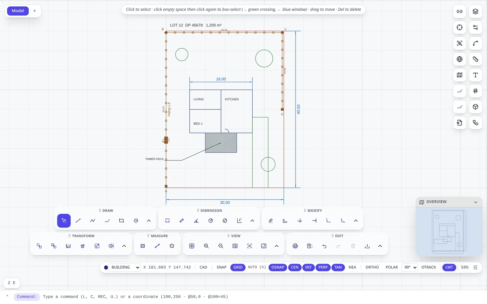
*Figure 3.1 — The editor with the Lot 12 sample drawing.*
1. **Layout tabs** — *Model* is the drawing; **+** adds a paper sheet.
2. **Hint bar** — tells you what the current tool expects next.
3. **Panel rail** — opens Layers, Properties, Blocks, Fences, GIS and other panels.
4. **Canvas** — the drawing. Red and green lines are the X and Y axes.
5. **Draw · Dimension · Modify** tool groups.
6. **Transform · Measure · View · Edit** tool groups.
7. **Overview** — a minimap; drag the frame to move around.
8. **Status bar** — layer, coordinates and drafting toggles.
9. **Command line** — type any command or coordinate here.
### Tool groups
The floating tool groups at the bottom hold the most-used tools. Hover any button to see its name and command. The **˄** arrow at the end of a group expands it to show the less common tools. Drag a group by its **⠿** handle to move it anywhere on screen; it snaps neatly to the edges and to other groups. You can restore the default arrangement from *Settings → Editor defaults → Toolbar layout → Reset to default*.
| Group | Contains |
| --- | --- |
| **Draw** | Select, line, polyline, fence, rectangle, circle — expanded: arc, ellipse, spline, polygon, point, ray, construction line, revision cloud, text, multiline text, table. |
| **Dimension** | Linear, aligned, angular, radius, diameter, ordinate — expanded: arc length, continue, baseline, leader. |
| **Modify** | Erase, offset, trim, extend, fillet, chamfer — expanded: break, join, lengthen. |
| **Transform** | Move, copy, mirror, rotate, scale, stretch — expanded: align, array, edit polyline, divide, measure. |
| **Measure** | Hatch, distance, area. |
| **View** | Zoom and pan controls, including zoom window and zoom extents. |
| **Edit** | Plot, page setup, undo, redo, delete selection, export. |
### The panel rail
The column of round buttons on the right opens the side panels. Panels are floating cards: drag them by their header, close them with **×**. The same panels open from the command line (for example `LA` for Layers).
- **Share** link and **Layers**
- **Object snap** settings and **Properties**
- **Groups** and **Linetypes**
- **Georeference** and **Dimension styles**
- **GIS / map** and **Text styles**
- **Fences** and **Fence elevation**
- **Grid**, **Blocks**, **Import**, **External references**
The Properties panel also opens by itself whenever you select something (you can switch that off with its **Auto-open** box).
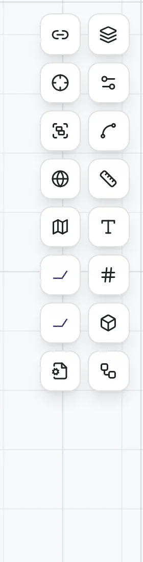
*Figure 3.2 — The panel rail.*
### The status bar
Highlighted (filled) buttons are **on**; click any of them to toggle.
| Item | Meaning |
| --- | --- |
| **Layer list** | The current layer — new objects are drawn on it. |
| **X / Y** | Live cursor coordinates. When the drawing is georeferenced they show grid **E**/**N**. |
| **CAD / MAP** | The current environment (see Chapter 17). |
| **SNAP · GRID** | Grid snap and grid display. **AUTO (5)** shows the grid spacing. |
| **OSNAP · CEN INT PERP TAN NEA** | Object snap on/off and the individual snap modes. |
| **ORTHO · POLAR 90° · OTRACK** | Ortho lock, polar tracking (with its angle) and object-snap tracking. |
| **LWT** | Display lineweights on screen. |
| **58%** · ☰ | Zoom level and display settings. |
---
## Chapter 4: Commands & coordinates
*The heart of BranchCAD*
Everything in BranchCAD can be done from the command line. Clicking a toolbar button and typing its command do exactly the same thing — use whichever is faster for you.
### Running a command
1. Type the command or its alias — `LINE` or just `L` — and press `Enter`. Commands are not case-sensitive.
2. Read the prompt on the left of the command line, e.g. *LINE: Specify next point or [Close/Undo]*. Words in brackets are **options**; type the capital letter (`C`, `U`) to use one.
3. Answer by clicking in the drawing or typing a value or coordinate, and press `Enter`.
4. Press `Enter` on an empty line (or right-click) to finish. Press `Enter` again to **repeat** the last command. `Esc` cancels.
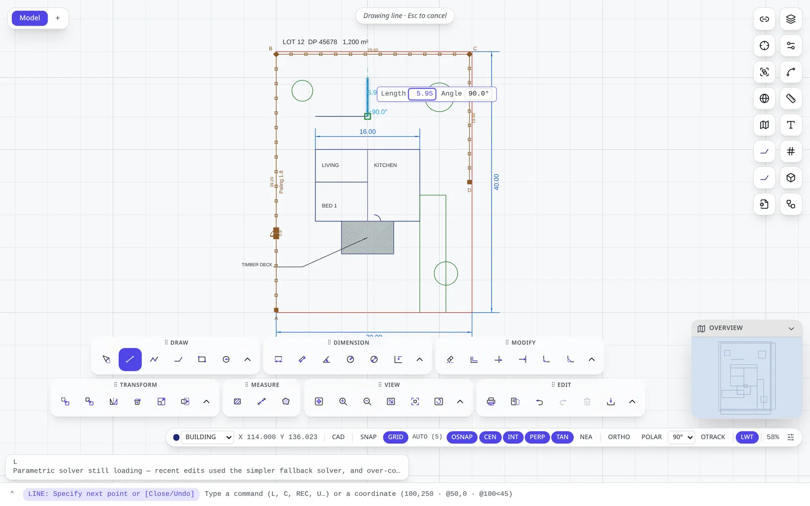
*Figure 4.1 — Drawing a line. The prompt reads LINE: Specify next point or [Close/Undo]; the dynamic input box beside the cursor shows the length and angle of the segment being drawn.*
### Typing coordinates
Wherever a command asks for a point you can type it instead of clicking. Angles are in degrees, measured counter-clockwise from the positive X axis (east = 0°, north = 90°).
| Form | Example | Meaning |
| --- | --- | --- |
| `x,y` | `100,250` | Absolute point, measured from the origin. |
| `@dx,dy` | `@50,0` | Relative — 50 to the right of the last point. |
| `d **Dynamic input:** While drawing, the **Length** and **Angle** boxes next to the cursor accept typing too. Combine them with **ORTHO** or **POLAR** to draw exact lengths in exact directions without typing any commas.
### Options that work inside commands
| Type | In | Effect |
| --- | --- | --- |
| `U` | any point-by-point command | Undo the last point (LINE removes the last segment). |
| `C` | LINE, PLINE, SPLINE, FENCE, AREA, REVCLOUD | Close the shape back to its start. |
| `D` | CIRCLE | Enter a diameter instead of a radius. |
| `I` / `C` | POLYGON | Inscribed in / circumscribed about a circle. |
| `S` / `R` | INSERT | Scale / rotate the block you are placing. |
| `DE P T DY` | LENGTHEN | Delta, Percent, Total, Dynamic. |
| `C O J W F S D R` | PEDIT | Close, Open, Join, Width, Fit, Spline, Decurve, Reverse. |
While a command is waiting for one of its options, those letters belong to the command — typing `C` at a POLYGON prompt chooses *Circumscribed* and does not start the CIRCLE command.
### Commands that act on a selection
Many commands work **noun-first**: select the objects, then type the command. `GROUP`, `UNGROUP`, `EXPLODE`, `ERASE`, `REGION`, `UNION`, `SUBTRACT`, `INTERSECT`, `LAYISO` and `FENCEAPPLY` all act on whatever is selected. Modify commands such as `MOVE` and `ROTATE` use the current selection if there is one, and ask you to select otherwise.
---
## Chapter 5: Navigating the drawing
*Moving around*
| Action | How |
| --- | --- |
| Zoom in / out | Roll the **mouse wheel** — zooming centres on the cursor. Or press `+` / `−`, or type `Z I` / `Z OUT`. |
| Pan | Hold `Space` and drag, use the **Pan** tool (`P`), or nudge with the arrow keys. |
| See everything | `Z E` (or `ZE`, `Z A`, bare `Z`) — zoom extents. |
| Zoom to an area | `Z W` then drag a box. |
| Zoom to the selection | Select, then `Z O`. |
| Go back | `Z P` — the previous view. |
| Realtime zoom | `Z R` then drag up / down. |
| Jump with the overview | Drag the frame in the **Overview** minimap; collapse it with its arrow. |
### Saved views
Type `V` (or `VIEW`) to open **Saved views**. Frame the part of the drawing you want, type a name such as *Front yard* and click **Save**. Click a saved view later to jump straight back to it. Saved views are stored with the drawing, so collaborators see them too.
`NAV` opens the navigation settings, where you can adjust mouse-wheel behaviour and turn smooth zoom animation on or off.
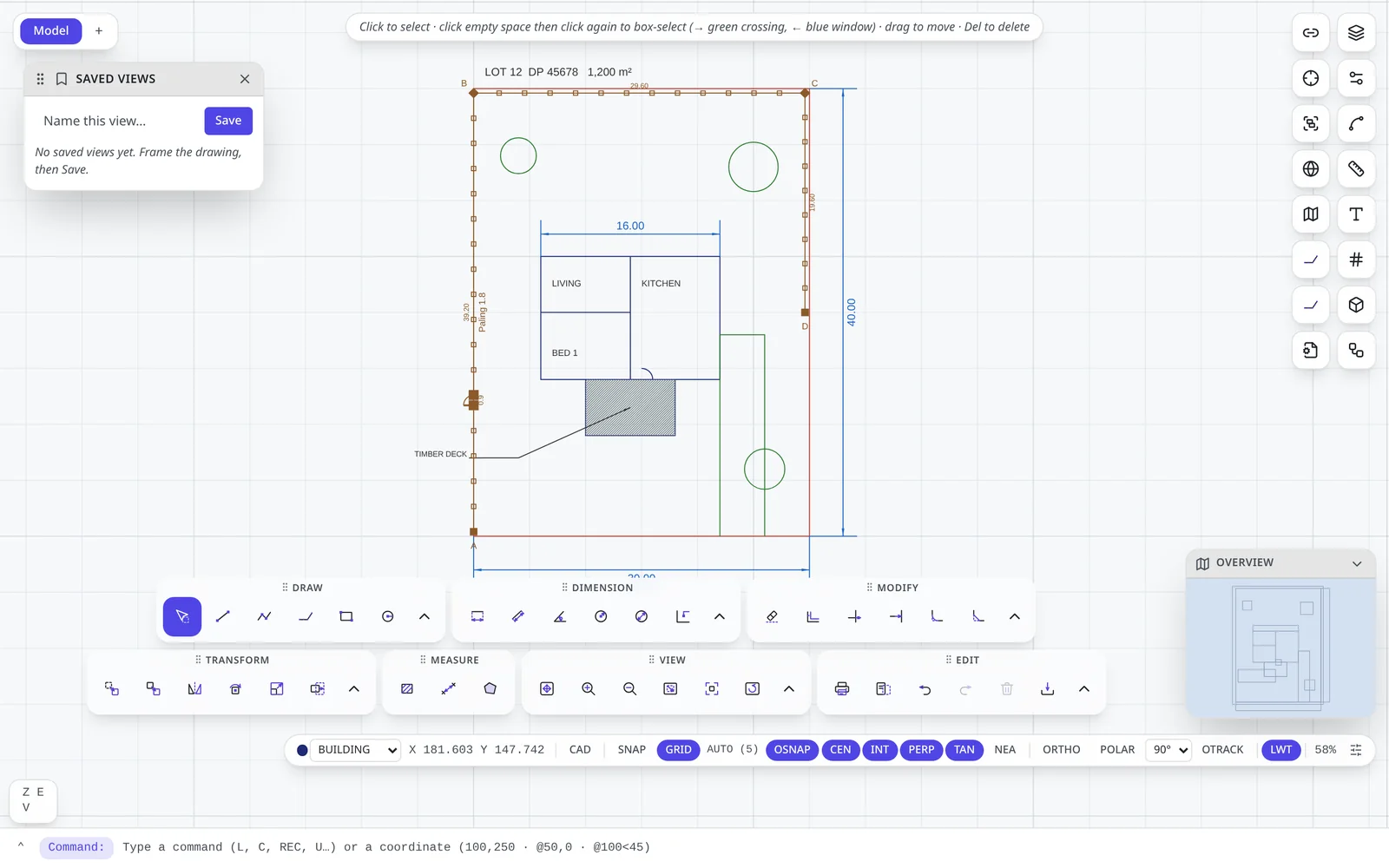
*Figure 5.1 — The Saved views panel.*
---
## Chapter 6: Drawing objects
*Creating geometry*
Every drawing tool follows the same rhythm: start the command, give it points (by clicking or typing), and finish with `Enter`. New objects go on the current layer shown on the status bar.
| Command | Aliases | How to use it |
| --- | --- | --- |
| **LINE** | `L` | Click a start point, then each next point. Each segment is a separate line. `C` closes, `U` undoes a segment. |
| **PLINE** | `PL` | Like LINE, but all segments form one polyline object. `C` makes it closed. |
| **RECTANG** | `REC` | Two opposite corners. Use `@w,h` for the second corner to give exact width and height. |
| **CIRCLE** | `C` | Centre, then radius (or `D` then diameter). |
| **ARC** | `A` | Start point, a point on the arc, end point. |
| **ELLIPSE** / **ELLIPSEARC** | `EL` / `EA` | Centre and the two axis ends; the arc form also asks for start and end angles. |
| **SPLINE** / **SPLINEFIT** | `SPL` / `SPF` | A smooth curve by control vertices, or one that passes through every point you click. |
| **POLYGON** | `POL` | Number of sides, centre, `I` or `C`, then radius. |
| **POINT** | `PO` | Place point markers. `DDPTYPE` chooses the marker style and size. |
| **RAY** / **XLINE** | `RAY` / `XL` | Construction lines infinite in one or both directions. |
| **REVCLOUD** | `RC` | Click around an area to mark a revision; `C` closes the cloud. |
| **TEXT**, **MTEXT**, **TABLE** | `T`, `MT`, `TB` | See Chapter 11. |
| **FENCE** | `FN` | See Chapter 18. |
### Example — a house outline with internal walls
1. Choose the **BUILDING** layer from the status bar.
2. `REC` `Enter` `6,14` `Enter` `@16,11` `Enter` — the outside of the house.
3. `L` `Enter` `14,14` `Enter` `@0,11` `Enter` `Enter` — a wall between bedroom and kitchen.
4. `L` `Enter` `6,20` `Enter` `@8,0` `Enter` `Enter` — the living-room wall.
5. `A` `Enter` and click three points to draw a door swing.
> **Tip:** To change a finished object, select it and edit any value in the Properties panel — coordinates, radius, width, height, vertices. You never need to redraw to fix a dimension.
---
## Chapter 7: Drafting precision
*Accuracy*
### Object snaps
With **OSNAP** on, the cursor locks onto exact points of existing objects. A marker and a tooltip show what it found — for example *Endpoint · 8.38 < −162.6°* — before you click.
| Snap | Finds |
| --- | --- |
| Endpoint | The ends of lines, arcs and polyline segments. |
| Midpoint | The middle of a segment. |
| Center (CEN) | The centre of a circle, arc or ellipse. |
| Quadrant | The 0°, 90°, 180° and 270° points of a circle. |
| Intersection (INT) | Where two objects cross. |
| Perpendicular (PERP) | The point at right angles from your last point. |
| Tangent (TAN) | A tangent point on a curve. |
| Nearest (NEA) | The closest point on any object. |
| Extension · Parallel | Points along a line's extension, or parallel to a segment you hover. |
Turn individual snap modes on or off on the status bar. The crosshair button on the panel rail opens the full object-snap settings.
### Grid and snap
| Command | Effect |
| --- | --- |
| `GRID` or `F7` | Show / hide the grid. |
| `GRID 5` | Draw grid lines every 5 units. |
| `GRID A` | Automatic spacing that adapts to the zoom level (**AUTO** on the status bar). |
| `SNAP` or `F9` | Toggle snapping the cursor to the grid. |
| `SNAP 0.5` | Cursor moves in steps of 0.5. |
| `GRID LOCK ON/OFF` | Whether setting a grid spacing also sets the snap step. |
### Ortho, polar and tracking
- **ORTHO** (`F8`) — the cursor moves only horizontally or vertically from the last point.
- **POLAR** (`F10`) — the cursor locks to multiples of the polar angle shown on the status bar (e.g. 90°, 45°, 30°). Choose the angle from the list beside it.
- **OTRACK** (`F11`) — object-snap tracking: hover a snap point, move away, and the cursor tracks along alignment lines from it.
> **Example — exact lengths without typing coordinates:** Turn on ORTHO, start `L`, click a start point, move the cursor to the right and type `12` `Enter`; move it up and type `4.5` `Enter`. You have drawn a 12 × 4.5 corner.
---
## Chapter 8: Selecting & the Properties panel
*Choosing what to change*
### Ways to select
| Action | Result |
| --- | --- |
| Click an object | Selects it; the Properties panel opens. |
| Click more objects | Adds them to the selection. |
| Click empty space, then click again to the **right** | Green crossing box — selects everything the box touches. |
| Click empty space, then click again to the **left** | Blue window box — selects only what is fully inside. |
| `Ctrl`+`A` | Select all. |
| `Esc`, `Ctrl`+`D` | Clear the selection. |
| Drag a selected object | Moves it. |
| `Del` | Erases the selection. |
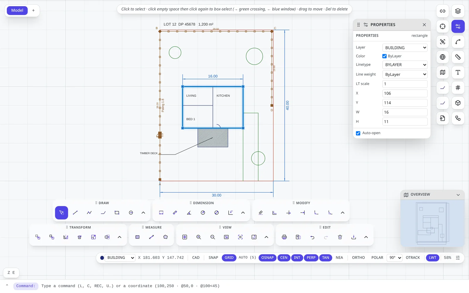
*Figure 8.1 — The house rectangle selected. Its layer, colour, linetype, lineweight, position and size are all editable.*
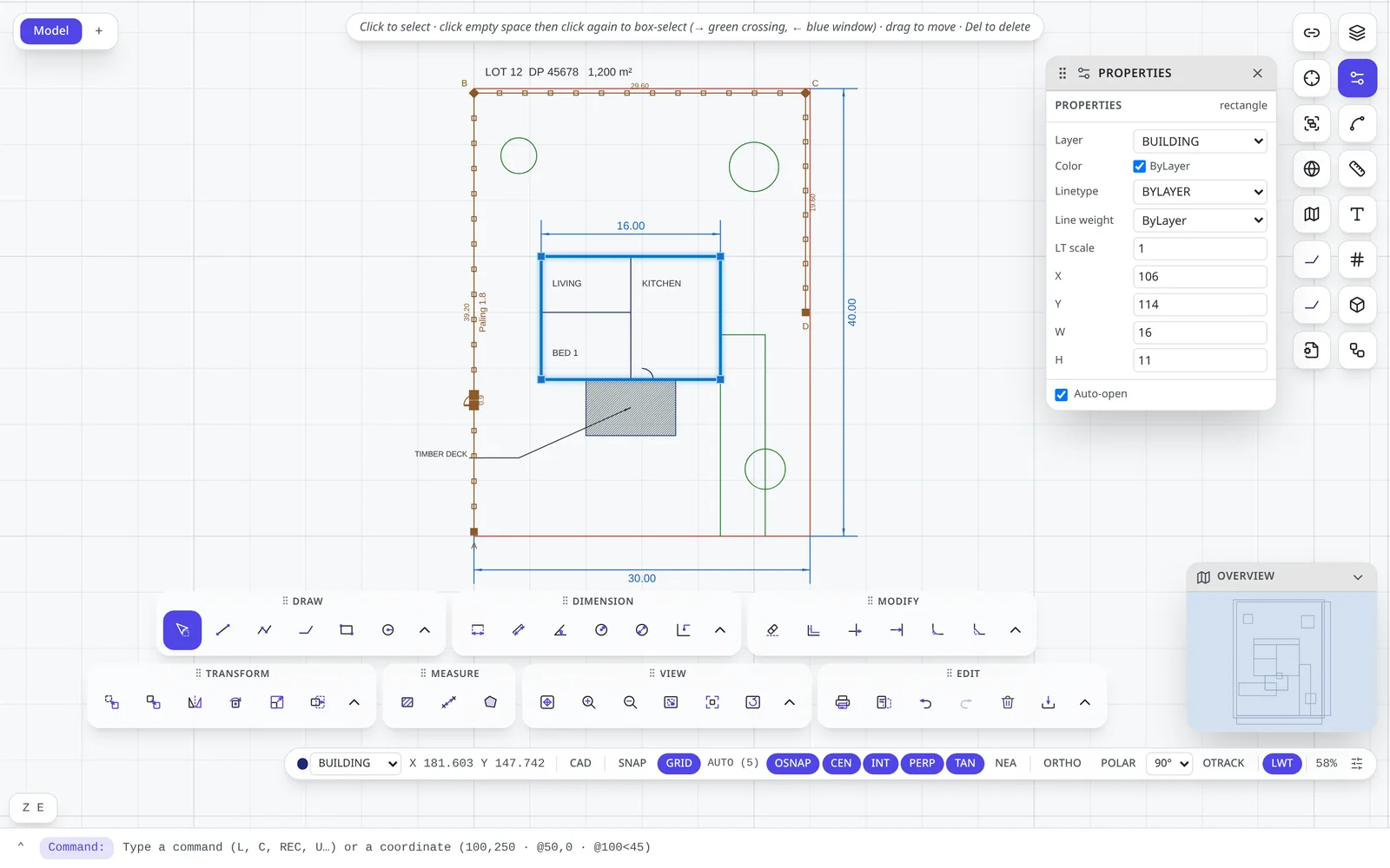
*Figure 8.2 — Grips: the blue squares on a selected object. Drag one to reshape the object.*
### The Properties panel
Every object type has its own properties. Change a value and press `Enter` (or click away) and the drawing updates at once. Common to all objects: **Layer**, **Color** (tick *ByLayer* to follow the layer), **Linetype**, **Line weight** and **LT scale**. Below that are the geometry fields — for example *X, Y, W, H* for a rectangle, centre and radius for a circle, and a vertex table (with insert and delete) for polylines, splines and revision clouds. Text, tables, dimensions, hatches and fences have the richest sections. When several objects are selected, the panel edits the values they share.
### Quick select
Type `QSELECT` (`QSE`) to select by property. Choose a **Type**, **Layer**, **Linetype**, **Color** and an optional **Length** range; the dialog shows how many objects match before you click **Select**.
**Example:** select every circle on the LANDSCAPE layer — Type = Circle, Layer = LANDSCAPE, **Select** — then change their colour in the Properties panel in one go.
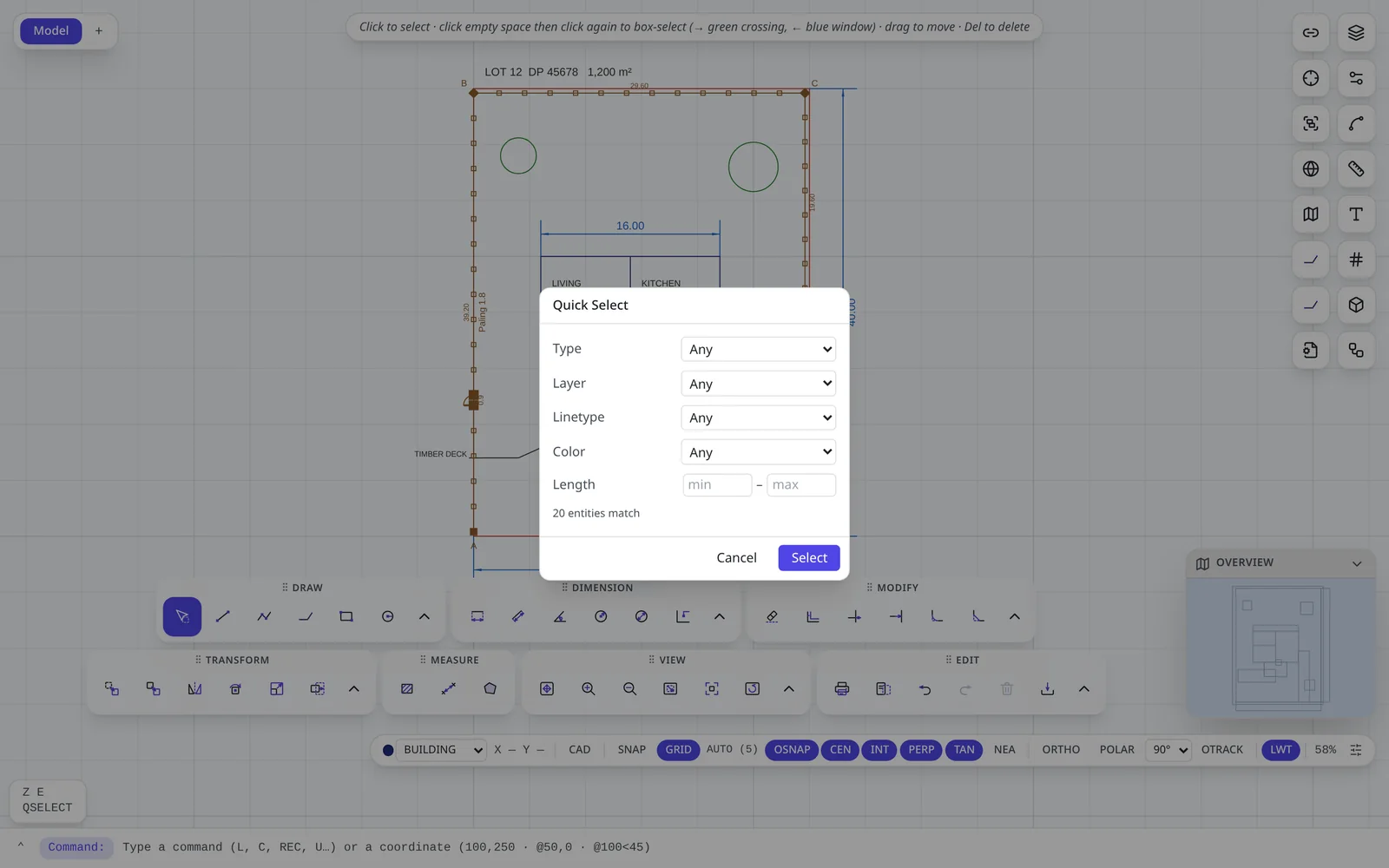
*Figure 8.3 — Quick Select.*
### Groups
Select objects and type `GROUP` (`G`) to bind them into a named group that selects as one. `UNGROUP` dissolves it. `GROUPS` opens the group manager, where you can rename, select or remove groups.
---
## Chapter 9: Modifying geometry
*Editing*
| Command | Alias | What it does · how |
| --- | --- | --- |
| **MOVE** | `M` | Select, base point, destination. *M ⏎ (select) ⏎ 0,0 ⏎ @5,0* |
| **COPY** | `CO`, `CP` | As MOVE, but leaves the original. Keeps placing copies until `Esc`. |
| **ROTATE** | `RO` | Base point, then an angle (typed or picked). |
| **SCALE** | `SC` | Base point, then a factor — `2` doubles, `0.5` halves. |
| **MIRROR** | `MI` | Two points defining the mirror line. |
| **OFFSET** | `O` | Distance, pick an object, click the side. Repeats until `Esc`. |
| **TRIM** | `TR` | Click each piece to cut away at its nearest crossing. |
| **EXTEND** | `EX` | Click near an end to extend it to the next object. |
| **FILLET** | `F` | Pick two objects to join with a rounded (or sharp, radius 0) corner. |
| **CHAMFER** | `CHA` | Pick two objects to join with a bevelled corner. |
| **BREAK** | `BR` | Split an object at one point or remove the part between two. |
| **JOIN** | `J` | Join touching lines and arcs into one polyline. |
| **STRETCH** | — | Window the vertices to move; they move, the rest stays. |
| **LENGTHEN** | `LEN` | Change a length by Delta, Percent, Total or Dynamically. |
| **ALIGN** | `AL` | Two source and two target points; optionally scale to fit (`Y`/`N`). |
| **ARRAY** | `AR` | Rows and columns, or copies around a centre. |
| **PEDIT** | `PE` | Close/Open, Join, Width, Fit, Spline, Decurve, Reverse a polyline. |
| **EXPLODE** | `X` | Break blocks, polylines and dimensions into their parts. |
| **DIVIDE** / **MEASURE** | `DIV` / `ME` | Place points dividing an object into N parts, or every N units along it. |
| **MATCHPROP** | `MA` | Copy layer, colour, linetype etc. from one object to others. |
| **ERASE** | `E`, `DEL` | Delete the selection (or press `Del`). |
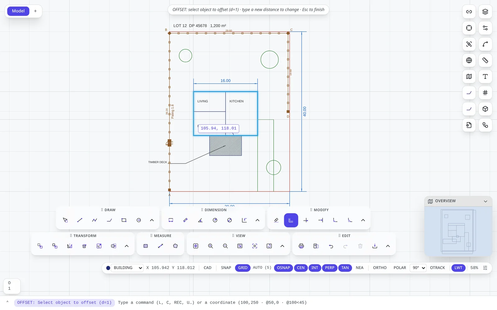
*Figure 9.1 — OFFSET with a distance of 1: hovering the house highlights it and shows where the offset copy will go. The prompt reads OFFSET: Select object to offset (d=1).*
> **Example — a 1 m eaves line round the house:** `O` `Enter` `1` `Enter`, click the house, click outside it, `Esc`. Then select the new rectangle and set its Linetype to *DASHED* in Properties.
---
## Chapter 10: Layers, linetypes & lineweights
*Organisation*
Layers are how you organise a drawing: put boundaries, buildings, dimensions and notes on separate layers so you can colour, hide, lock and plot them independently.
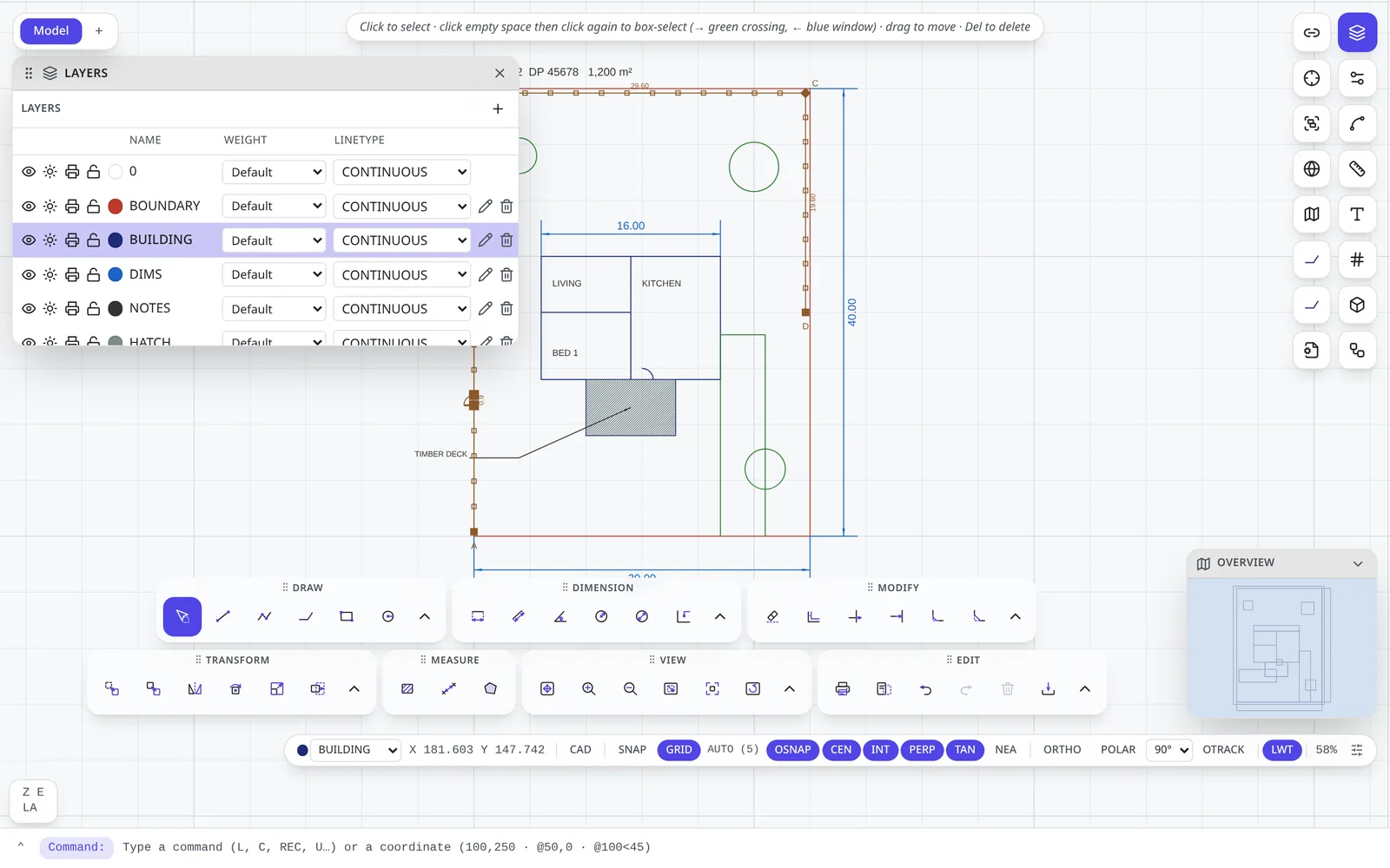
*Figure 10.1 — The Layers panel (`LA`). The highlighted row is the current layer.*
### The Layers panel
Each row has, from the left: **on/off** (eye), **freeze** (sun), **plot** (printer), **lock** (padlock), the layer **colour**, its **name**, **lineweight** and **linetype**, then **rename** and **delete**. Click **+** to add a layer. Click a row to make it current.
- **Off** hides a layer. **Frozen** also hides it and excludes it from selection everywhere.
- **Locked** layers stay visible but cannot be selected or edited — ideal for a survey you trace over.
- Turning **plot** off keeps a layer on screen but leaves it out of PDFs.
### Layer commands
| Command | Effect |
| --- | --- |
| `LAYISO` | Isolate: show only the layers of the selected objects. |
| `LAYUNISO` | Restore the visibility from before LAYISO. |
| `LAYMRG` | Merge the selected objects' layers into the current layer. |
| `LAYDEL` | Delete the selected objects' layers **together with everything on them**. |
### Linetypes
`LT` opens the Linetype panel: *CONTINUOUS, DASHED, DOTTED, CENTER, HIDDEN, DASHDOT* and more. Assign a linetype to a layer or to individual objects. `LTSCALE` (`LTS`) sets how long the dashes are across the whole drawing; each object's own **LT scale** fine-tunes it.
### Lineweights
Set lineweights per layer in the Layers panel or per object in Properties. Turn on **LWT** on the status bar to see them on screen; they always apply when you plot.
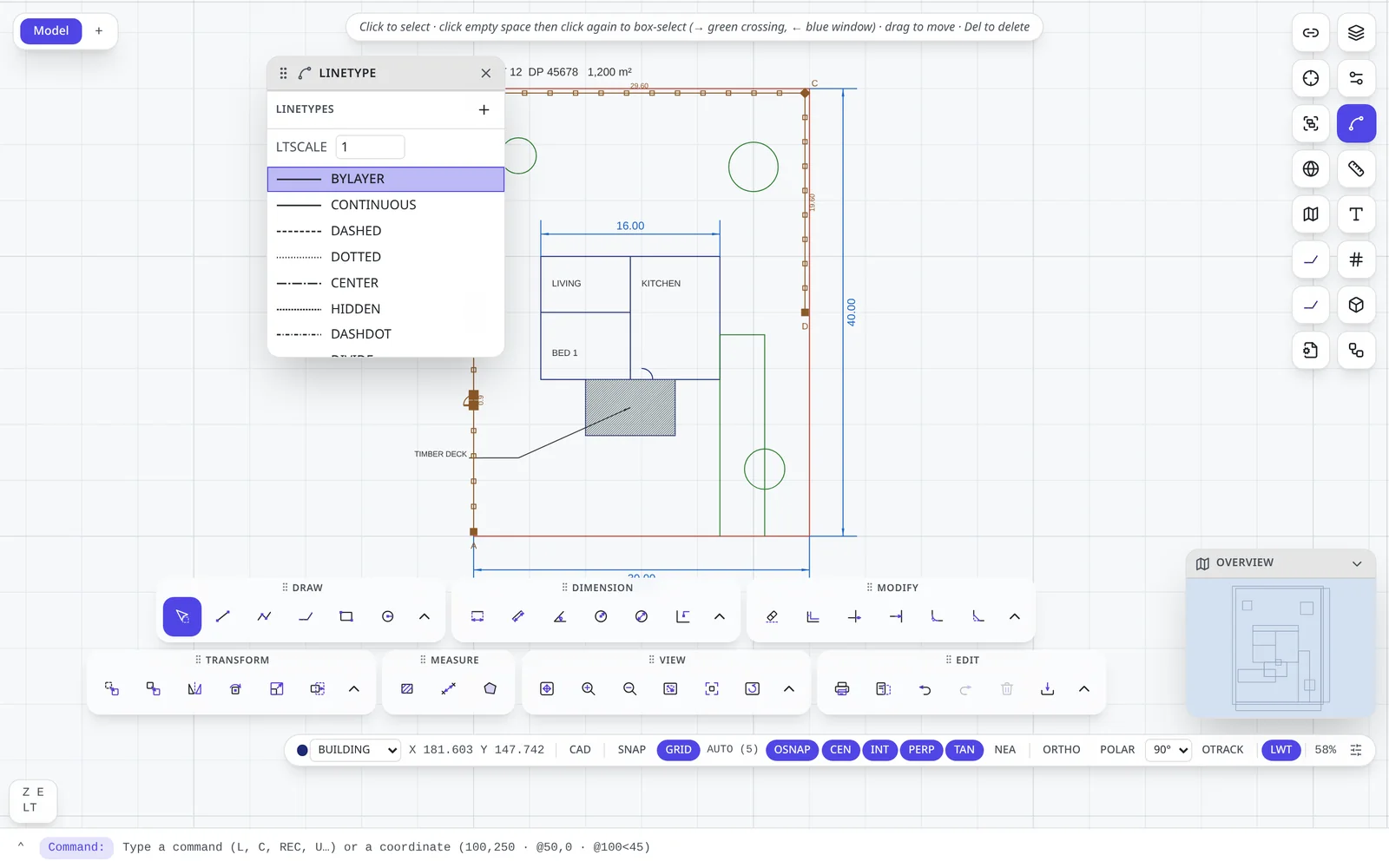
*Figure 10.2 — The Linetype panel and LTSCALE.*
---
## Chapter 11: Text, tables & leaders
*Annotation*
| Command | How to use it |
| --- | --- |
| **TEXT** (`T`) | Click where the text starts and type directly in the drawing. `Enter` finishes. Double-click any text later to edit it in place. |
| **MTEXT** (`MT`) | Drag a box; type a paragraph that wraps to the box width. Bold, italic and other formatting are available while editing. |
| **TABLE** (`TB`) | Click to place a table. Double-click a cell to type in it; set rows, columns, sizes and cell alignment in Properties. |
| **LEADER** (`LE`, `MLD`) | Click the arrow tip, a bend point and the end; then type the note. In the sample drawing, *TIMBER DECK* is a leader. |
| **STYLE** (`ST`) | Text styles: font, fixed height, width factor, oblique angle, bold and italic. New text uses the current style. |
| **UPDATEFIELD** | Recalculate field values inside block attributes (e.g. an area or date in a title block). |
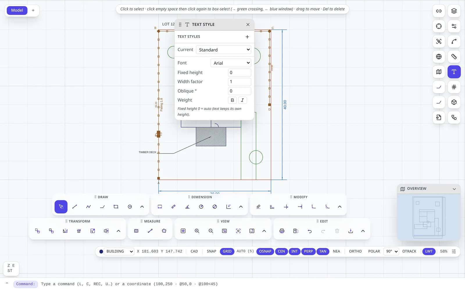
*Figure 11.1 — The Text Style panel. A fixed height of 0 lets every text object keep its own height.*
> **Tip:** Change the content, height, rotation and justification of any text from the Properties panel — select several labels at once to make them all the same height.
---
## Chapter 12: Dimensions
*Annotation*
Dimensions are associative: when the geometry they measure changes, the dimension follows and its value updates.
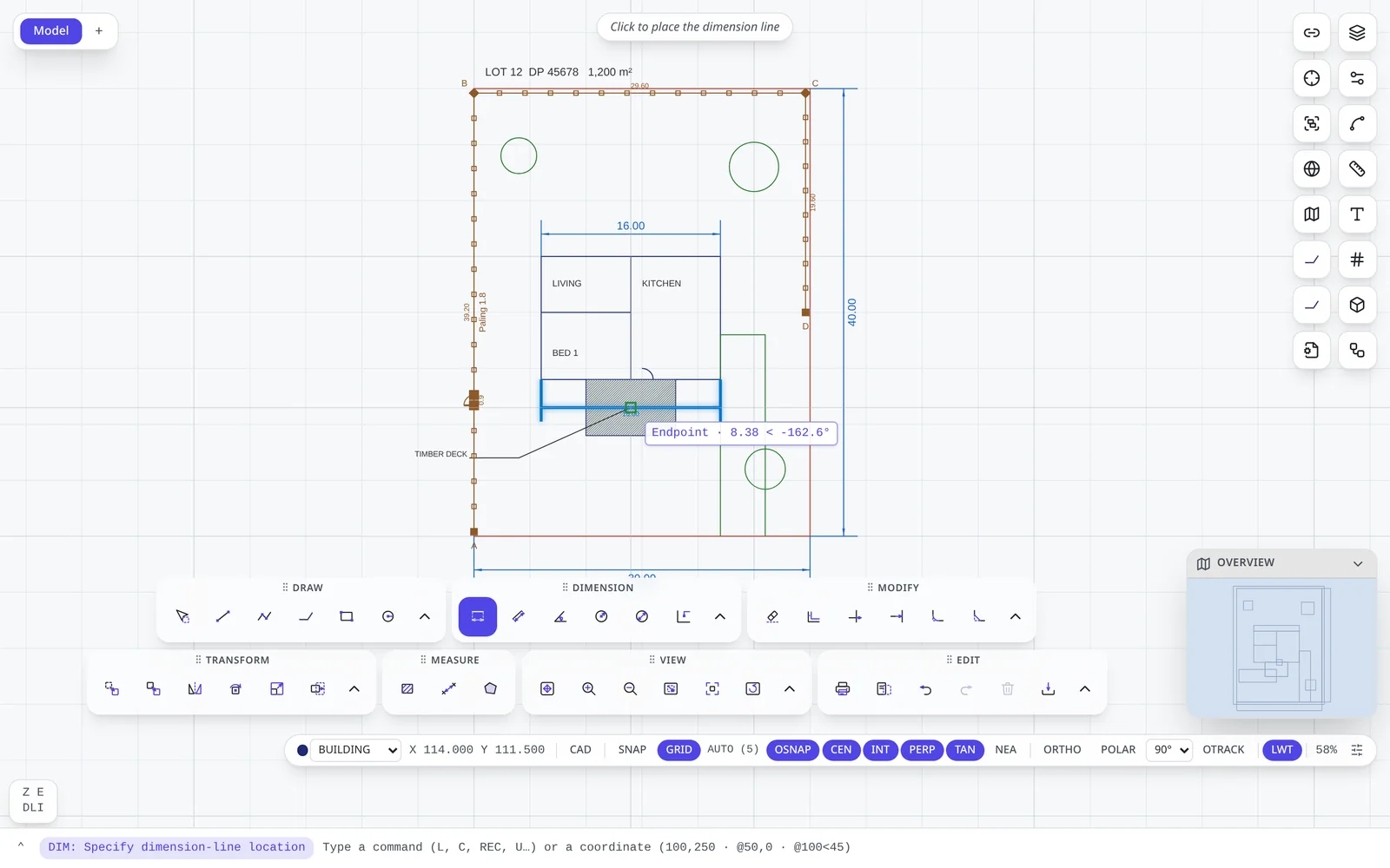
*Figure 12.1 — DIMLINEAR: the two points have been picked on the house corners (snapped to Endpoint) and the dimension line follows the cursor until you click to place it.*
| Command | Alias | Measures |
| --- | --- | --- |
| **DIMLINEAR** | `DLI` | Horizontal or vertical distance — direction follows your drag. |
| **DIMALIGNED** | `DAL` | True distance, parallel to the two points. |
| **DIMANGULAR** | `DAN` | The angle between two lines. |
| **DIMRADIUS** / **DIMDIAMETER** | `DRA` / `DDI` | Radius or diameter of a circle or arc. |
| **DIMORDINATE** | `DOR` | X or Y coordinate of a feature from the datum. |
| **DIMARC** | `DAR` | The length along an arc. |
| **DIMBASELINE** | `DBA` | More dimensions from the same baseline as the last one. |
| **DIMCONTINUE** | `DCO` | A chain of dimensions end-to-end. |
### Dimension styles
`DIMSTYLE` (`D`) opens the Dim Style panel. A style controls text height and scale, arrow size and type, extension-line offset and extension, text gap, baseline spacing, precision and angle precision, units, text colour, and whether extension lines are suppressed. Create a style with **+**, choose it as **Current**, and new dimensions use it.
To override one dimension, select it and change its text, size or arrows in Properties.
> **Tip:** Use **Text scale** to make one style read well at different plot scales — e.g. 1 for 1:100 sheets, 2.5 for 1:250.
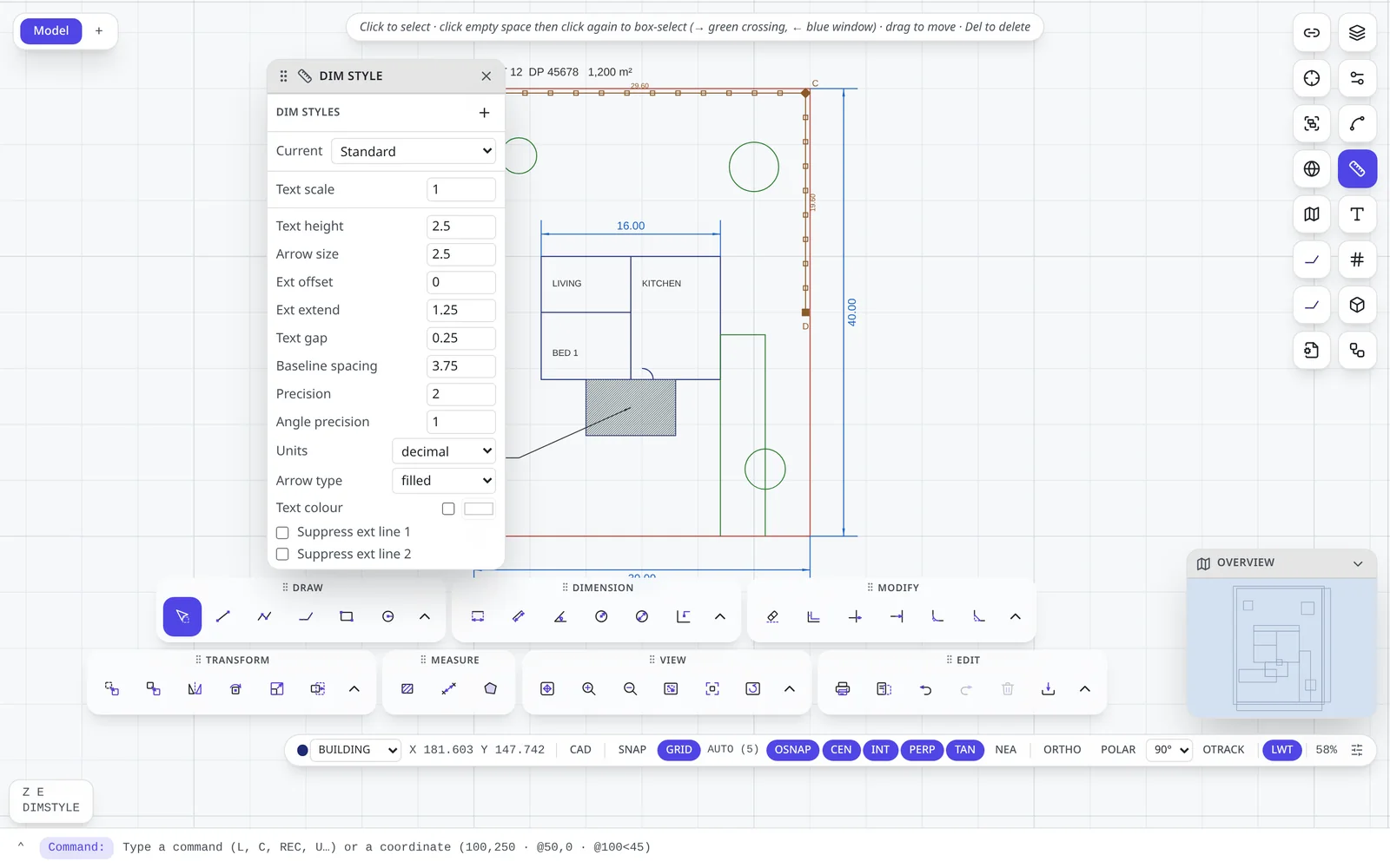
*Figure 12.2 — The Dim Style panel.*
---
## Chapter 13: Hatching & regions
*Fills & areas*
### Hatching an area
1. Type `H` (or click **Hatch** in the Measure group). The prompt reads *HATCH: Click on or inside a closed boundary to fill it*.
2. Click inside any closed area. BranchCAD finds the boundary itself — including islands inside it, which are left unfilled.
3. Select the hatch to change its **Pattern** (ANSI31, EARTH, SOLID and others), **Angle**, **Scale** and **Line weight**, or type `HE` to edit it.
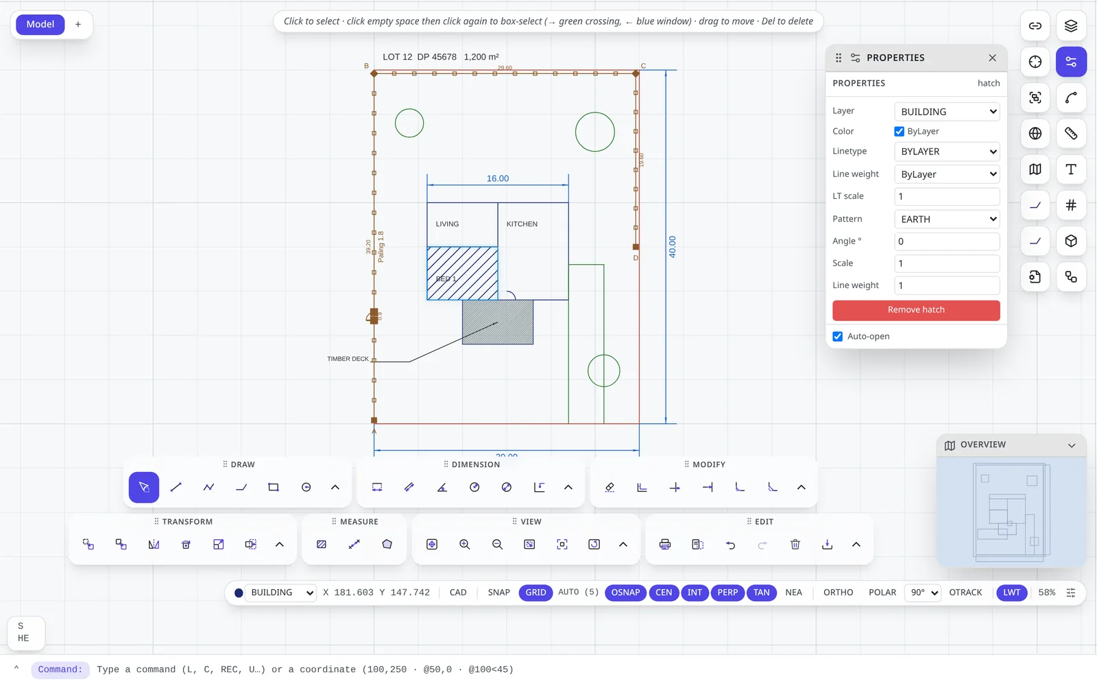
*Figure 13.1 — Bedroom 1 hatched with a single click and the hatch's properties open. Remove hatch deletes it.*
Hatches are associative: move or stretch the boundary and the hatch refills to match.
### Regions and boolean shapes
A **region** is a filled area that can have holes. Select closed shapes and type `REGION` (`REG`, `BO`) to convert them. Then combine regions:
- `UNION` (`UNI`) — merge into one shape.
- `SUBTRACT` (`SU`) — cut the others out of the first one you selected.
- `INTERSECT` (`INT`) — keep only the overlap.
> **Example:** Draw the section boundary and the house footprint, convert both to regions, and SUBTRACT the house from the section: the result is the open-space region, whose area is shown in Properties.
---
## Chapter 14: Blocks, images & external references
*Reuse*
### Blocks
A block is a named, reusable symbol. Every drawing starts with a library of built-in blocks such as *BH, SPT, CPT, PILE, ANCHOR* and *FOOTING*.
1. Type `I` (`INSERT`) to open the Blocks panel.
2. Click **Insert** beside a block. It follows the cursor.
3. Type `S` to set a scale or `R` to set a rotation, then click to place it.
To make your own block, select the objects and type `B` (`BLOCK`), or click **Define** in the panel. **Explode** (or `X`) turns an inserted block back into separate objects. Blocks may carry **attributes** — text values such as a tag or a level — that you fill in for each insert.
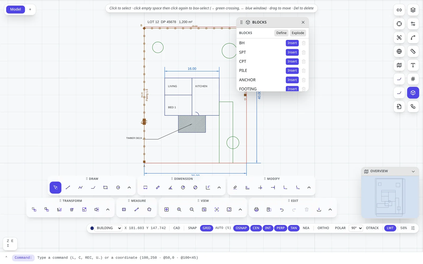
*Figure 14.1 — The Blocks panel.*
### External references (XREFs)
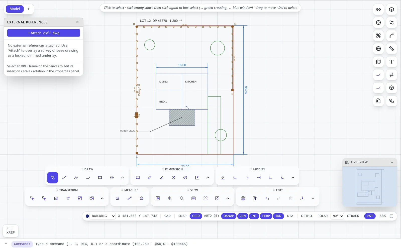
*Figure 14.2 — The External references panel.*
An XREF overlays another DXF or DWG file — a survey, a base plan from an architect — as a locked, dimmed underlay that you can snap to but not accidentally edit.
- `XREF` (`XR`) opens the manager; `XATTACH` (`XA`) or **+ Attach .dxf / .dwg** picks a file.
- Select an XREF frame to set its insertion point, scale and rotation in Properties.
- `XBIND` copies the XREF's contents into your drawing permanently; `XDETACH` removes it.
### Raster images
Type `IMAGE` (`IAT`) to attach a PNG or JPEG — a scanned plan or a photo — and place, scale and rotate it like any object. Images can be traced over with snaps and are included in plots.
---
## Chapter 15: Measuring
*Inquiry*
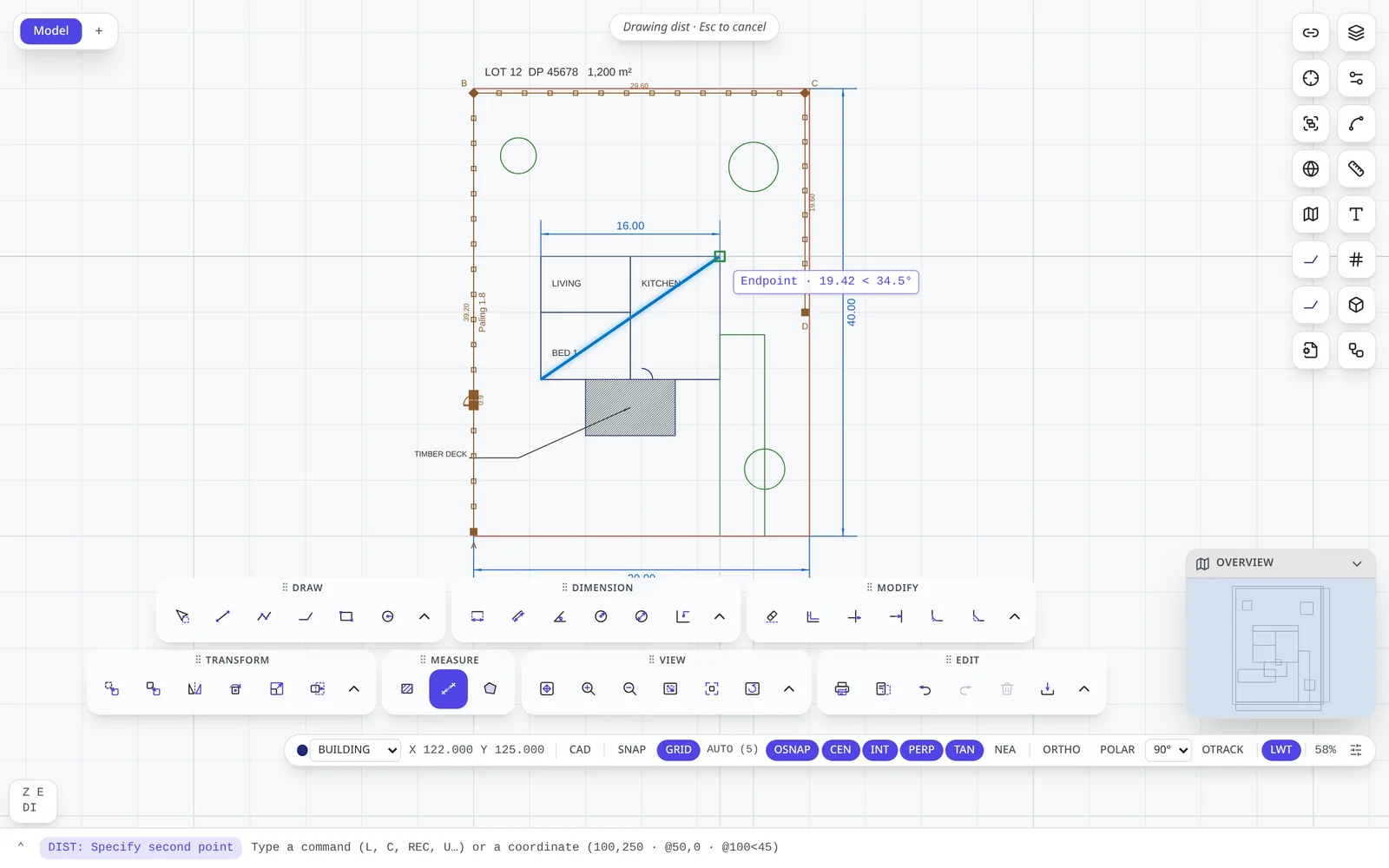
*Figure 15.1 — DIST: after picking the first point, the tooltip shows the live distance and angle (19.42 < 34.5°) to the snapped second point.*
| Command | Use |
| --- | --- |
| **DIST** (`DI`) | Click two points. The command line reports the distance, the angle and the ΔX / ΔY between them. |
| **AREA** (`AA`) | Click the corners of an area and type `C` to close. Reports area and perimeter. |
| Properties panel | Select a closed polyline, circle, region or hatch to read its area and length directly; select a fence to read its total length and number of gates. |
---
## Chapter 16: Layouts, sheets & plotting
*Output*
Draw at full size in **Model** space; arrange it on paper in a **layout**. A layout is a sheet of paper with one or more **viewports** — scaled windows onto the model.
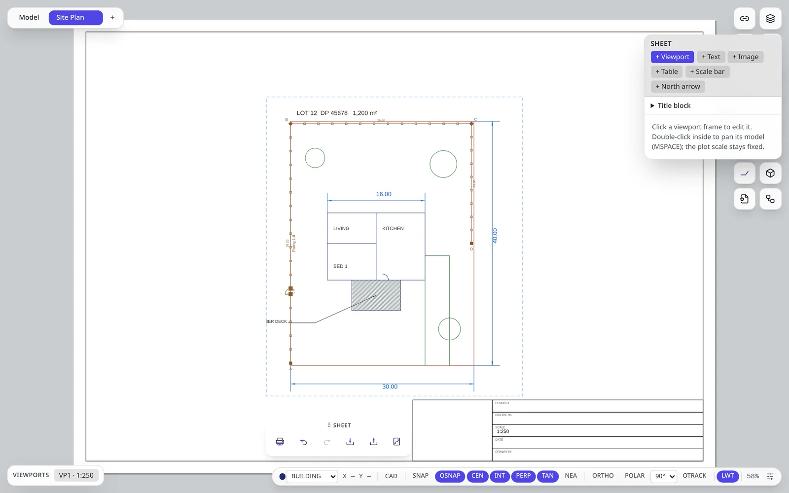
*Figure 16.1 — The Site Plan layout: an A3 landscape sheet with a 1:250 viewport (bottom left), a title block, and the Sheet panel for adding viewports, text, images, tables, a scale bar and a north arrow.*
### Making a sheet
1. Click **+** next to the *Model* tab, or type `LAYOUT` (`LO`). Name the sheet and choose a paper size and orientation.
2. Click **+ Viewport** in the Sheet panel (or type `MVIEW`) and drag the viewport frame on the paper.
3. Select the viewport and set its **scale** (e.g. 1:250) in Properties. Double-click inside it to pan the model while the scale stays fixed; click outside to return to the paper.
4. Fill in the **Title block** section — project, drawing title, scale, date, drawn by.
5. Add a **Scale bar** and **North arrow**; they read their scale and orientation from the viewport.
`PAGESETUP` edits the active sheet's paper size, margins and plot scale.
### Plotting to PDF
1. Type `PLOT` (or click the printer in the Edit group).
2. Choose the **Layout** to plot — the Model or any sheet.
3. Choose a **Colour mode**: Colour, or monochrome for clean black-on-white drawings.
4. Optionally open **Plot styles** (map colours to lineweights) or **Pen widths per layer**.
5. Click **Export PDF**.
The PDF is a true vector plot: line thicknesses are the assigned millimetre weights and text stays sharp at any zoom.
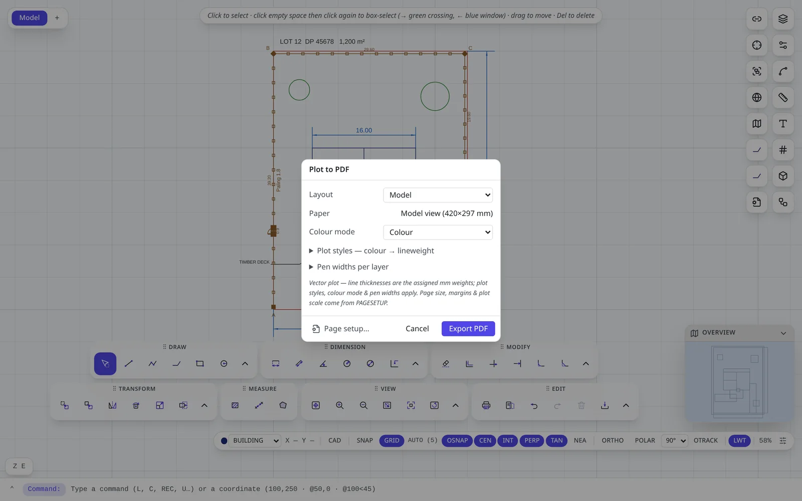
*Figure 16.2 — The Plot to PDF dialog.*
---
## Chapter 17: GIS & georeferencing
*Real-world location*
Georeferencing tells BranchCAD where your drawing sits on the earth. Your geometry stays in convenient local metres; BranchCAD translates to and from the map grid whenever you need it.
### Georeference a drawing
1. Type `GEOREF` (or click the globe on the panel rail).
2. Choose the **Coordinate system** — NZTM2000, the NZ meridional circuits, or MGA2020 / MGA94 zones for Australia.
3. Enter the **grid coordinate of local (0,0)**: the easting (E) and northing (N) where your drawing's origin belongs. **Round to 100 m** tidies the values.
4. Click **Apply**. The status changes to the CRS name, and the coordinate read-out shows E / N.
> **Nothing moves:** Applying a georeference does not move your drawing. It changes only the read-out, typed `G`easting,northing input, the Properties panel and exports in grid coordinates.
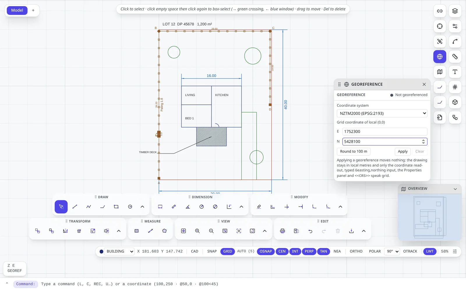
*Figure 17.1 — The Georeference panel with NZTM2000 selected.*
### Working in grid coordinates
Once georeferenced, type a grid coordinate with a `G` prefix wherever a point is asked for: `L` `Enter` `G1752300,5428100` `Enter` `@20<90` `Enter` draws a line from that survey mark straight north for 20 m.
### The GIS panel
Type `GIS` to open the GIS panel (currently available for New Zealand, New South Wales and Queensland):
- **Basemap imagery** — show satellite imagery (with or without labels) or a street map under your drawing. Imagery is drawn in the drawing's own projection.
- **Address** search (`ADDRESS`) — type at least three characters to find a property and frame it.
- **Parcels** — type `PARCEL` and click inside a property: its legal boundary is inserted on locked GIS layers, with its appellation.
- **Building outlines** — type `BUILDING` (`BLDG`) and click a house to insert its footprint as a closed polyline. The tool stays active, so click the next house to grab it too. Footprints are indicative, not survey-accurate.
### Map mode
Type `MAP` to switch the editor to an **interactive map environment** — satellite, streets or terrain that you can pan, zoom and rotate, with your drawing overlaid in place. Type `CAD` to return to the CAD canvas. `AOI` (`MAPAREA`) lets you drag a rectangle to restrict the map to an **area of interest**.
**GIS data in and out:** `CSVIN` imports a CSV point schedule, `GEOJSONIN` imports GeoJSON features, and `DXFOUT GRID` exports a DXF in real grid coordinates (Chapter 19).
---
## Chapter 18: Fence design
*Specialist tools*
A fence in BranchCAD is a single intelligent object. You draw the path and choose a fence type; BranchCAD generates the posts, rails, infill, gates, elevation and material list — and regenerates them every time you edit the path.
### The fence library
Type `FT` (`FENCETYPE`) to open the **Fences** panel. Fence types are grouped — *Boundary*, *Front fences*, *Pool*, *Rural* — each with a thumbnail and height, for example *Timber paling boundary 1.8 m*, *Picket front fence 1.1 m*, *Pool barrier 1.2 m*, *Steel sheet panel 1.8 m*, *Aluminium horizontal slat* and *Rural post and wire*. Search the library from the box at the top; **Details** shows the specification.
When a newer version of a type is available, an **Update** button appears on its card.
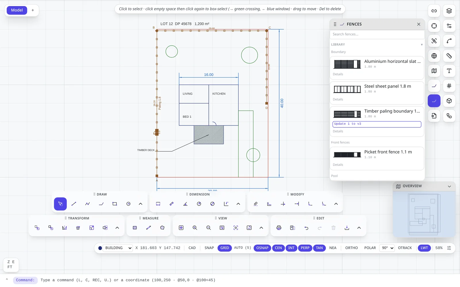
*Figure 18.1 — The Fences panel.*
### Drawing a fence
1. Click a fence type in the library to arm it (or drag its card onto a boundary or parcel to fence it in one go).
2. Type `FN` (`FENCE`) and click the corners of the fence, just like a polyline. `C` closes it into a loop; `Enter` finishes an open run.
3. Add gates: type `GATE` and click on the fence where the gate goes. Set the gate kind (pedestrian or driveway), width, number of leaves, hinge side and swing in Properties.
4. To change the type of existing fences, select them and type `FENCEAPPLY`, or pick another **Type** in Properties.
In plan, a fence shows its posts (end, corner, line and gate posts), corner letters (A, B, C…), the length of each side and a type tag such as *Paling 1.8*.
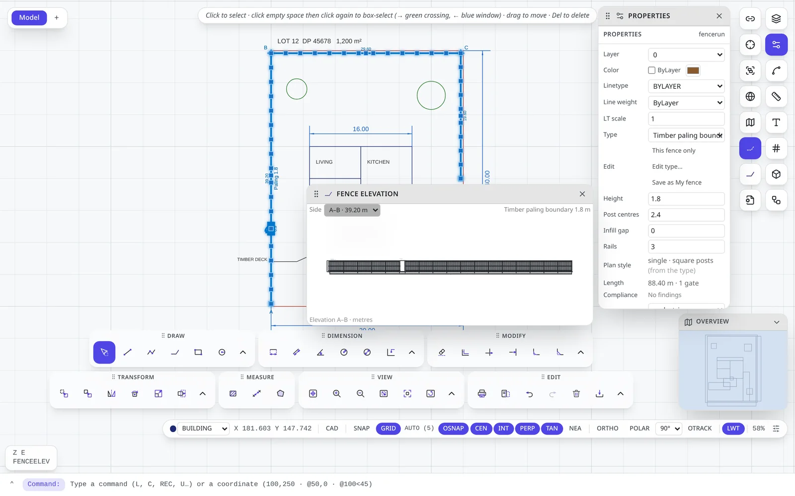
*Figure 18.2 — The boundary fence selected. Properties shows its type, height, post centres, rails, length (88.40 m · 1 gate) and compliance findings; the Fence elevation panel shows side A–B.*
### Elevations, designer and takeoff
- **Elevation** — select a fence and type `FEL` (`FENCEELEV`). Choose a side from the **Side** list to see posts, rails, palings, gates and dimension chains drawn to scale.
- **Per-fence adjustments** — change height, post centres, infill gap and number of rails for *this fence only* in Properties, or choose **Edit type…** / **Save as My fence** to create your own reusable type.
- **Fence designer** — `FENCEDESIGN` opens the designer for building a fence type from scratch.
- **Compliance** — rules such as pool-barrier requirements are checked as you draw; findings appear in Properties.
- **Bill of materials** — the Fences panel's BOM produces the quantities of posts, rails, palings, gates and hardware for the selected fences, ready to price.
---
## Chapter 19: Importing & exporting files
*Interoperability*
| Task | Command | Notes |
| --- | --- | --- |
| Open a DXF or DWG | `IMPORT`, `OPEN` | Brings the file's layers, blocks, text and dimensions into the current model. |
| Overlay a DXF/DWG | `XATTACH` | As a locked underlay (Chapter 14). |
| Export DXF | `EXPORT`, `DXFOUT`, `SAVEAS` | A standards-conformant DXF that opens in AutoCAD and other CAD programs. |
| Export DXF in grid coordinates | `DXFOUT GRID` | Coordinates translated to the drawing's CRS, for GIS use. |
| Import survey points | `CSVIN` | CSV point schedules. |
| Import GIS features | `GEOJSONIN` | GeoJSON points, lines and polygons. |
| Attach an image | `IMAGE` | PNG / JPEG raster. |
| PDF | `PLOT` | Vector PDF of the model or a sheet (Chapter 16). |
> **Tip:** After importing, type `Z E` to frame everything, then `LA` to review the layers that came in. Large DWG files can take a few seconds to read.
---
## Chapter 20: Sharing, collaboration & history
*Teamwork*
### Sharing a drawing
1. Click **Share** in the top bar. The *Share this drawing* dialog opens.
2. Choose the link permission: **Can view**, **Can comment** or **Can edit** (edit links need a paid plan).
3. Click **Create link** and **Copy** it — or type a **Recipient email** and click **Send**.
People with a view or comment link need no account. People with an edit link sign in (or create a free account) and then edit alongside you. The dialog lists every link with its status (*Active, Revoked, Expired*) and open count; **Revoke** stops a link at once. Every shared link supports up to 20 people at the same time.
### Editing together
- Everyone on the drawing appears as an avatar in the top bar, with a colour dot for *Editor* or *Viewer*, and a count such as *3 here*.
- Click someone's avatar to **Follow** them — your view tracks theirs. Click again to stop following.
- Changes appear for everyone instantly. If someone edits an object you have selected, it flashes so you notice.
- Each person's undo affects only their own changes.
### Comments
Click **Comments** in the toolbar. Click **+ Add**, click the spot on the drawing, type your comment and click **Comment**. Comments can be replied to, edited, **Resolved** and **Reopened**; filter the list by *Open, Resolved* or *All*, and click a comment to jump to its place in the drawing.
### Version history and branches
Click **History** in the top bar.
| To… | Do this |
| --- | --- |
| Mark a milestone | Type a name in **Version name** (e.g. *Rev C*) and click **Save**. Named versions are tagged *named* in the timeline. |
| See what changed | Click **Compare with previous** on a row, or tick two rows and click **Compare**. |
| Go back | Click **Restore** on a version and confirm. Restoring creates a new version — nothing is lost. |
| Try an alternative | Click **+ New branch from current**, name it (e.g. *Option B*) and click **Fork**. Use **Switch** to move between branches. |
| Bring a branch back | Click **Merge** on the branch, review any **Conflicts** and click **Apply merge**. |
| Recover recent work | Open **Auto-saves (recovery)** and click **Restore** on an entry. |
The **Branch tree** shows the history visually — click two nodes to compare them. Owners also see an **Activity** tab with an audit trail of who did what.
---
## Chapter 21: Settings & plans
*Personalising*
### Settings
| Section | Options |
| --- | --- |
| **Appearance** | Theme (Light, Dark, System, Custom), background, text colour, accent colour, font and interface size. |
| **Editor defaults** | Units (mm, cm, m, in, ft), show grid, object snap, autosave cadence (1–30 s), toolbar layout reset. |
| **Team** | For team accounts: add members and set roles — Owner, Admin, Editor, Viewer. |
| **Billing** | Your plan, invoices and payment details through the secure billing portal. |
| **Account** | Name, e-mail and verification, linked Google account, change password. |
### Plans
| Plan | Best for |
| --- | --- |
| **Free** | Learning and personal projects: view and comment links, a basic "what changed" comparison and 30 days of history. |
| **Pro** | Professionals: edit links, full version history, branching and the advanced visual comparison. |
| **Team** | Firms: shared workspace, member roles and everything in Pro. |
| **Enterprise** | Custom requirements — contact sales. |
See the **Plans** page for current prices; annual billing is discounted.
---
## Chapter 22: Keyboard shortcuts
*Reference*
| Keys | Action |
| --- | --- |
| `Enter` | Run / finish; repeat last command |
| `Esc` | Cancel command, clear selection |
| `Ctrl`+`Z` | Undo |
| `Ctrl`+`Y` · `Ctrl`+`Shift`+`Z` | Redo |
| `Ctrl`+`A` | Select all |
| `Ctrl`+`D` · `Ctrl`+`Shift`+`A` | Deselect all |
| `Ctrl`+`C` / `Ctrl`+`V` | Copy / paste |
| `Del` · `Backspace` | Erase selection |
| `+` / `−` | Zoom in / out |
| Arrow keys | Pan |
| `Space` + drag | Pan |
| Keys | Action |
| --- | --- |
| `F7` | Grid display |
| `F8` | Ortho |
| `F9` | Grid snap |
| `F10` | Polar tracking |
| `F11` | Object-snap tracking |
| Single-key tools (when the canvas has focus) |
| `S` · `L` · `R` | Select · Line · Rectangle |
| `C` · `A` · `E` | Circle · Arc · Ellipse |
| `T` · `D` · `G` | Text · Linear dim · Aligned dim |
| `P` | Pan |
> **Every command:** The full list of commands and aliases, with examples, is in the separate **BranchCAD Command Cheat Sheet**.
---
## Chapter 23: Troubleshooting & FAQ
*Help*
#### I typed a command and something else happened.
While a command is running, its option letters belong to it — e.g. `C` means *Close* inside LINE, not CIRCLE. Press `Esc` first to end the current command, then type the new one.
#### My clicks don't land where I expect.
Check the status bar: **SNAP** (grid snap) or **ORTHO** may be on, or an object snap may be catching a nearby point — watch the snap marker and tooltip before you click.
#### I can't select an object.
Its layer may be **locked** or **frozen**. Open `LA` and check the padlock and sun icons. Imported XREFs are locked by design.
#### I can't see my drawing.
Type `Z E`. If nothing appears, the layers may be off — open `LA`. If you used `LAYISO`, type `LAYUNISO`.
#### The dashes of a dashed line don't show.
Adjust `LTSCALE` — at large drawing sizes the dashes can be too small (or too large) to see.
#### My dimension text is tiny on the plot.
Increase the **Text scale** of the dimension style to suit your plot scale (Chapter 12).
#### Grid coordinates (`G…`) are rejected.
The drawing needs a georeference first — type `GEOREF`.
#### Map imagery or parcels don't load.
These need an internet connection and are available in New Zealand, New South Wales and Queensland. The drawing keeps working without them.
#### I went offline.
Keep working. The status shows *Offline · saved on this device* and everything is sent once you reconnect.
#### I made a mistake an hour ago.
Open **History** and **Restore** an earlier version, or use **Auto-saves (recovery)**. Restoring never deletes the newer work — it becomes part of the history.